GNS3 - Emulating Network Infrastructure on Debian 8.2
GNS3 (Graphical Network System 3) is an emulation software that let's you see the interaction of network devices in a network topology. It is mainly used for training in International Network Certifications and it is the Open source alternative to the Cisco Packet Tracer Software and it has some additional functions like interacting with Virtual Machines, Docker emulation, etc.
In this tutorial, I will show you the basis to install and operate this software. The GNS3 version that will be used in this tutorial is the 1.5.1, on a Debian 8.2 (Jessie) system.
Installation
I am using Core 2 Duo Intel PC with 4GB of RAM and 64-bit architecture, but I really advise you to use this software with a better computer, because it really demands a lot of memory and PC resources. The more complicated the topology is, the more resources will be demanded by GNS3.
First, you have to add this lines to your repository in the /etc/apt/sources.list archive:
deb http://ppa.launchpad.net/gns3/ppa/ubuntu xenial main
deb-src http://ppa.launchpad.net/gns3/ppa/ubuntu xenial main
And then run this commands:
sudo apt-key adv --keyserver keyserver.ubuntu.com --recv-keys A2E3EF7B
sudo apt-get update
sudo apt-get install gns3-gui
Then just wait until the software finishes the installation.
Using GNS3
You can run the program by clicking the program icon, or start it through the command in the console, and then this window will appear first:
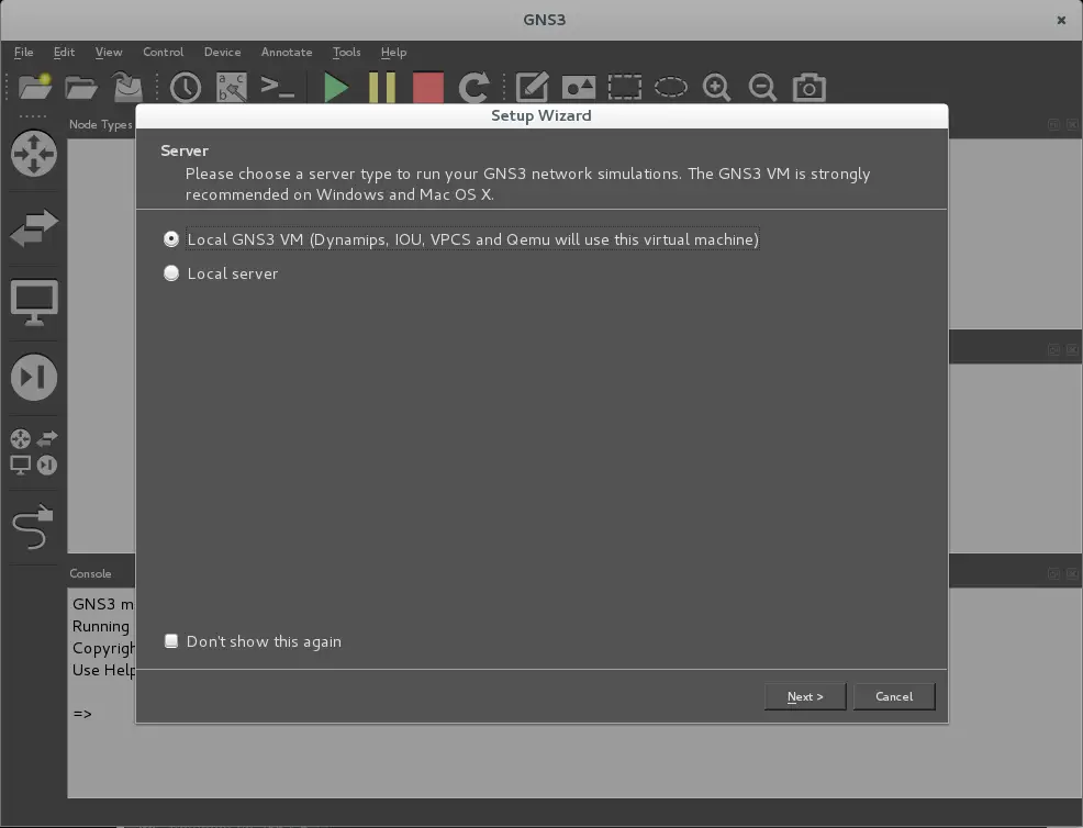
There are two options: the Local GNS3 VM choice that will use an external virtual machine to operate, and the other one that will let you select the local server running in your PC. In this tutorial, we will work mainly with Dynamips, the default local server for GNS3 that starts when you run your topology in the working window.
So you can press Next, and then the next screen will appear:
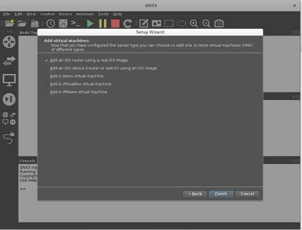
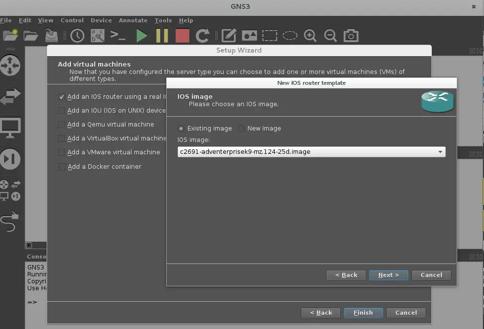
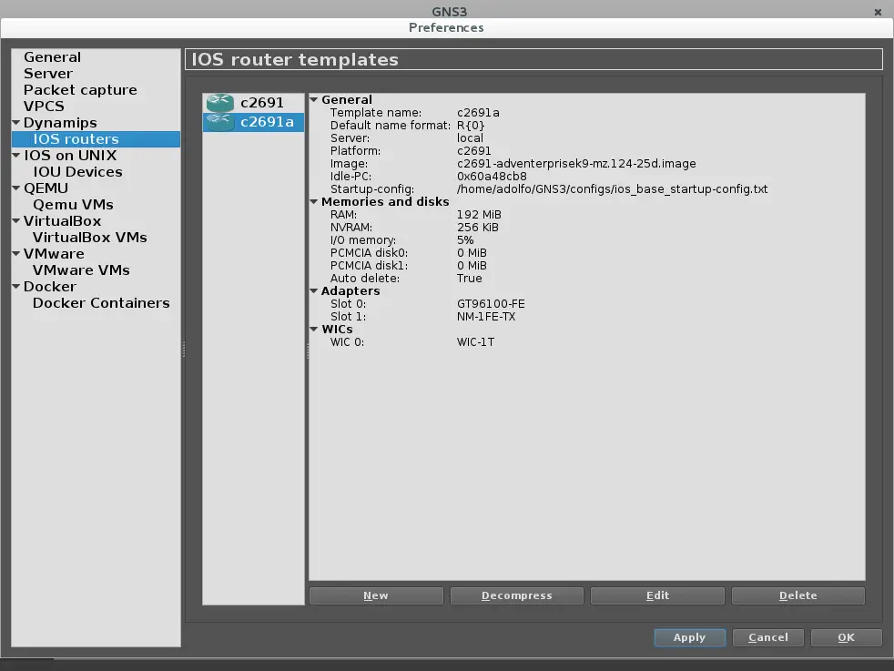
We will focus on using a basic topology made of two routers using some real IOS images with two host PC, so we will take the only marked option on the next screen, to add just one router model. Next, it will take you to select any existing Cisco IOS image on your PC. GNS3 works with some recommended Cisco IOS and they are described in this link. I will use one of those Cisco C2691 series IOS (c2691-adventerprisek9-mz.124-25d.bin) router images. In the next screen you must describe your IOS:
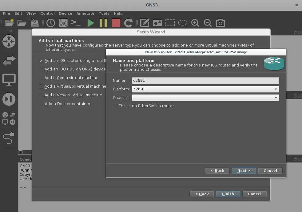
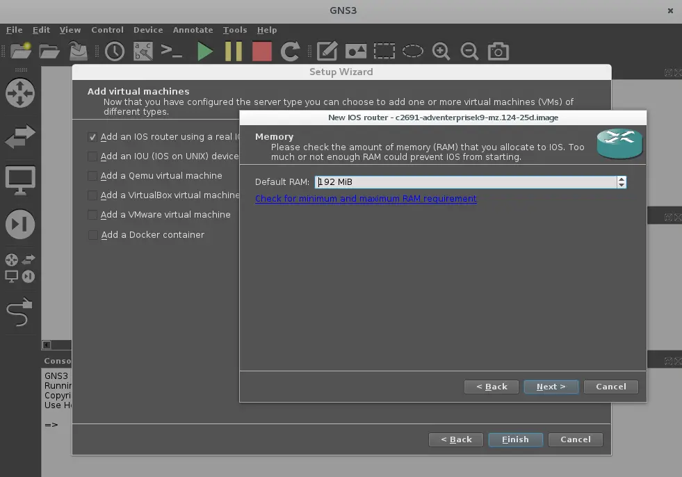
Now you have to define the amount of RAM memory from your PC that your emulated router will use. Just push next.
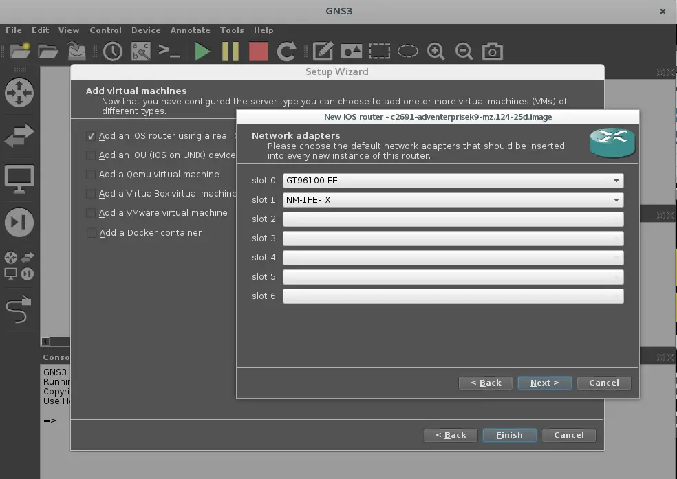
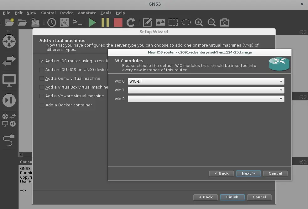
In the next window, we will define each card that will be used in the slots of the router. We will take one port ethernet card NM-1FE-TX for connecting virtual PC's in slot 1 (slot 0 has GT96100-FE by default) and one WIC-1T card to connect both routers through their wan port. Each card can be selected in the drop down menu on this window.
The next window will define the processing limits for each router in your topology, in order to prevent using the whole proccessing capacity from your PC. This option is named Idle-PC in GNS3, and it defines a unique number that represents a location of the memory address, which is not being used and can be defined for the use of the new device.
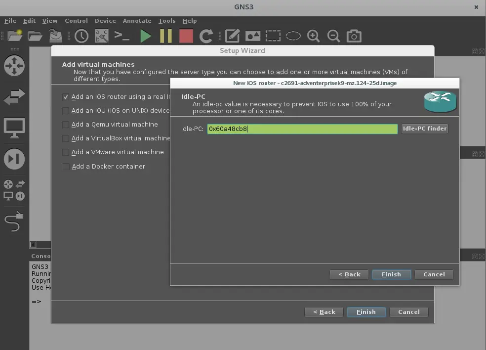
The green box tells you that the device is working fine, but if it turns red you must push the button Idle- PC finder in order to allow the computer to define the optimal parameters for this device to work, with available memory and PC load in the PC processor. If it goes well, the box turns green and will assign a new memory address, but if it doesn't, you must push Idle-PC finder button until it turns green, and show a valid address to select (this will be presented in a drop-down menu, where the optimal address value is marked with an asterisk).Then push the finish button and finish to go to the final window:
Then push the "apply" button and then Ok. The next step will let you define the name for your project and your working path. I advise you to select one created by yourself:
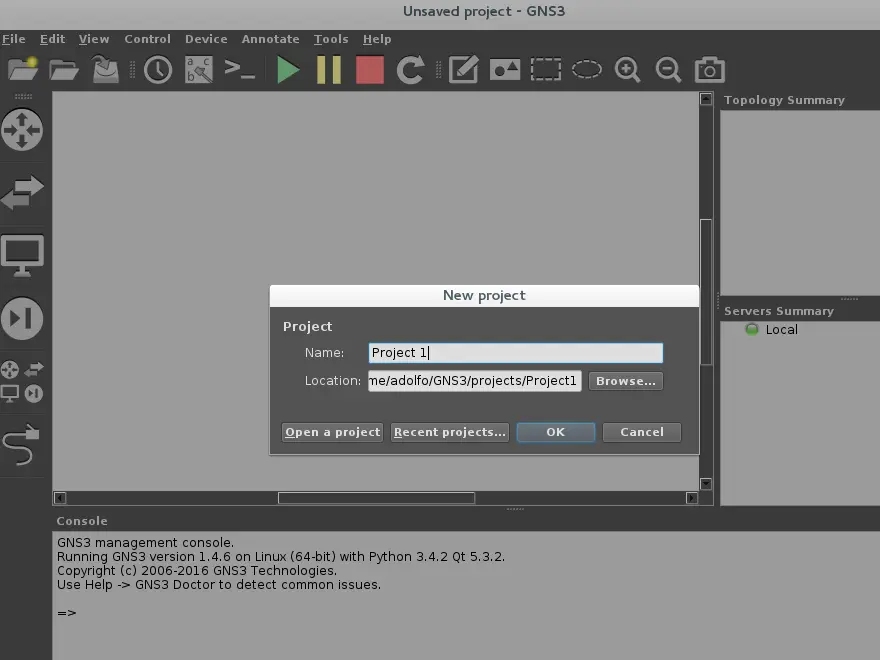
Then press ok, and finally you will be ready to start building your network topology.
Knowing the Interface
First, you must know the working interface:
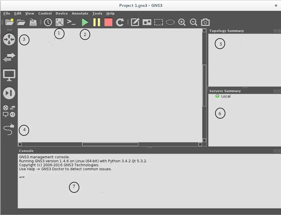
1. Show/Hide Interface label button, it toggles on/off the labels of any interface in devices of the network topology.
2.Start/Pause/Stop devices, each button starts/pause/stop the topology emulation. GNS3 works with an internal server named Dynamips, it is the main tool that emulates any networking device in the topology, and these buttons control the connection of every device in the topology to this server.
3.Device selection buttons. These buttons are used to take all devices that you will use in your topology.
![]() Router Selection Button.
Router Selection Button.
![]() Switch Selector Button
Switch Selector Button
![]() End Devices Selector Button. It will let you select Computers,cloud devices, etc.
End Devices Selector Button. It will let you select Computers,cloud devices, etc.
![]() Security Devices selector button.
Security Devices selector button.
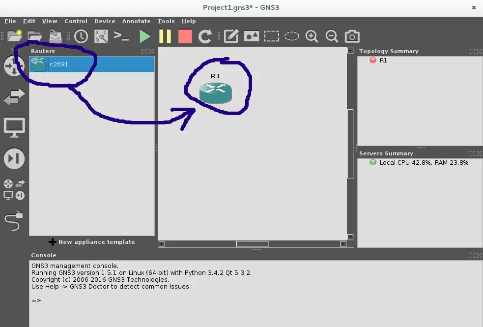
For instance, If you want to use a router from your list of devices, you have to push the router selection button and then a second window where all the routers whose IOS images have been added will appear.
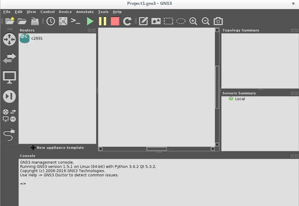
Now drag and drop the router, that you want to use, from the left list to your workspace.
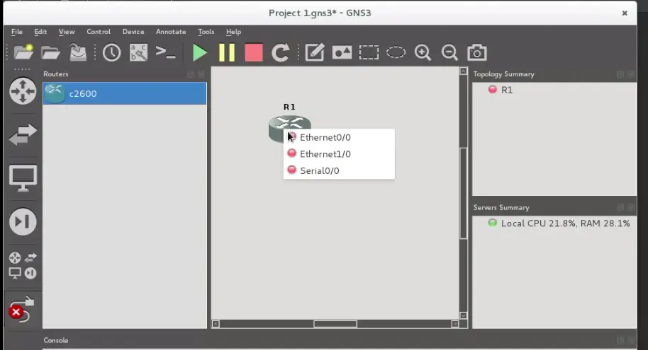
4. Add a Link button. It is used to make connections between devices. When you push this button, a cross cursor is shown, and when you click on the device from where you want to make a connection, a pop-up window will appear and you can select wich port of the enabled device is going to be used to make the link (Ethernet or Serial). I will show the use of this feature when we start to build the topology.
5. Topology summary: here you can see the status of any device that appears on the workspace. By default, the device starts in off status (represented by a red circle next to the name of this device).
6. Servers Summary: shows the status of the running server in your PC.
7. Management console.
Building a New Topology
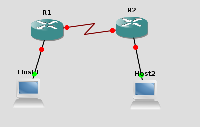
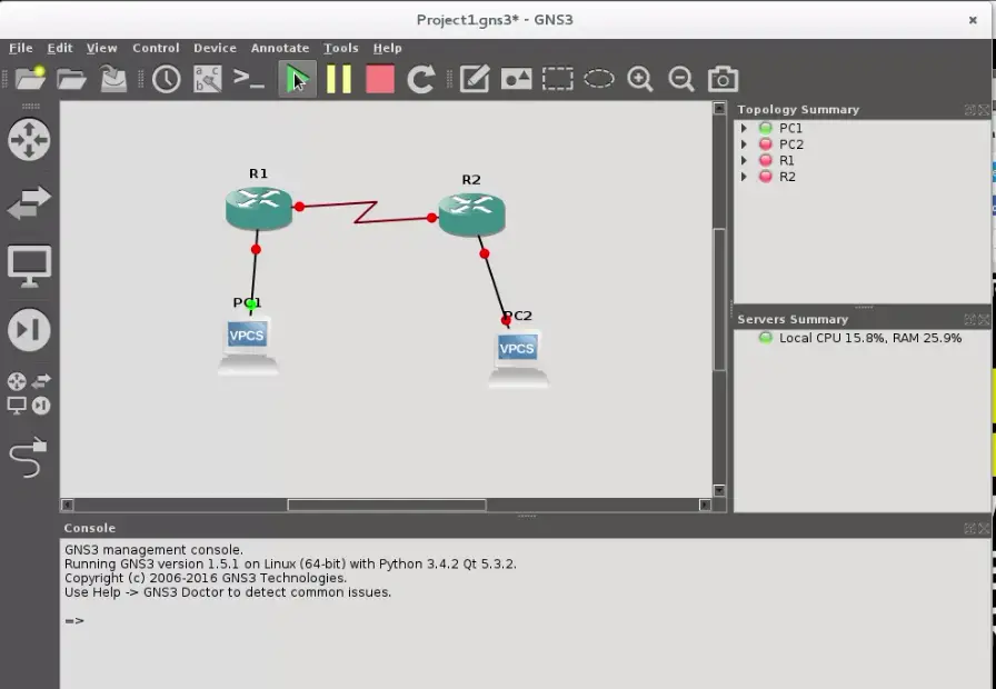
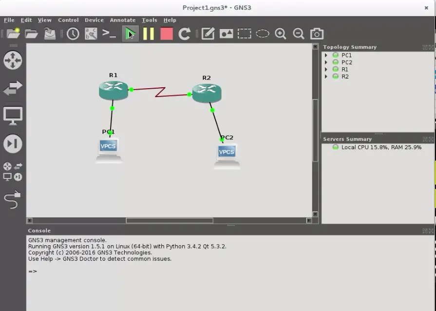
This is the topology that we want to build:
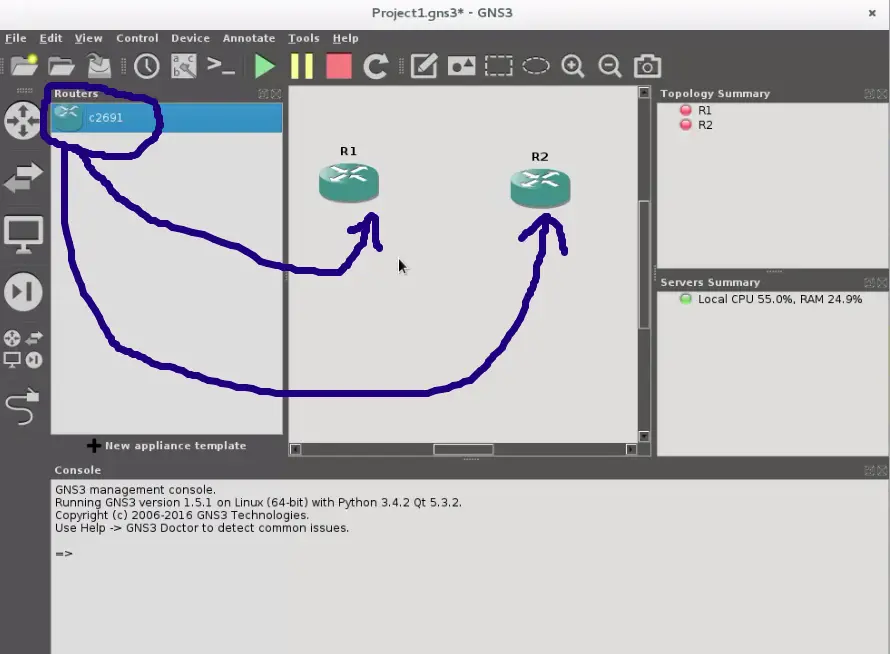
So let's add two routers, pushing the router selection button, and then drag and drop each element on the workspace:
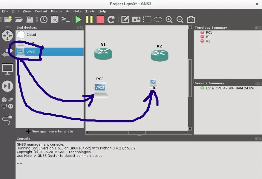
Do the same with the two hosts. I advise you to use VPCS, wich is a platform that emulates a PC in console mode and gives you commands to ping, trace route and many other features that help to test the new network topology.
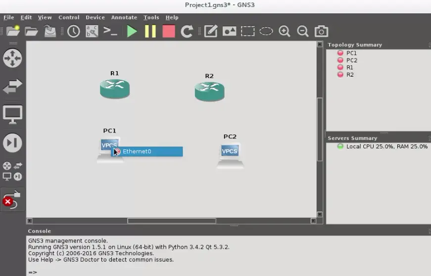
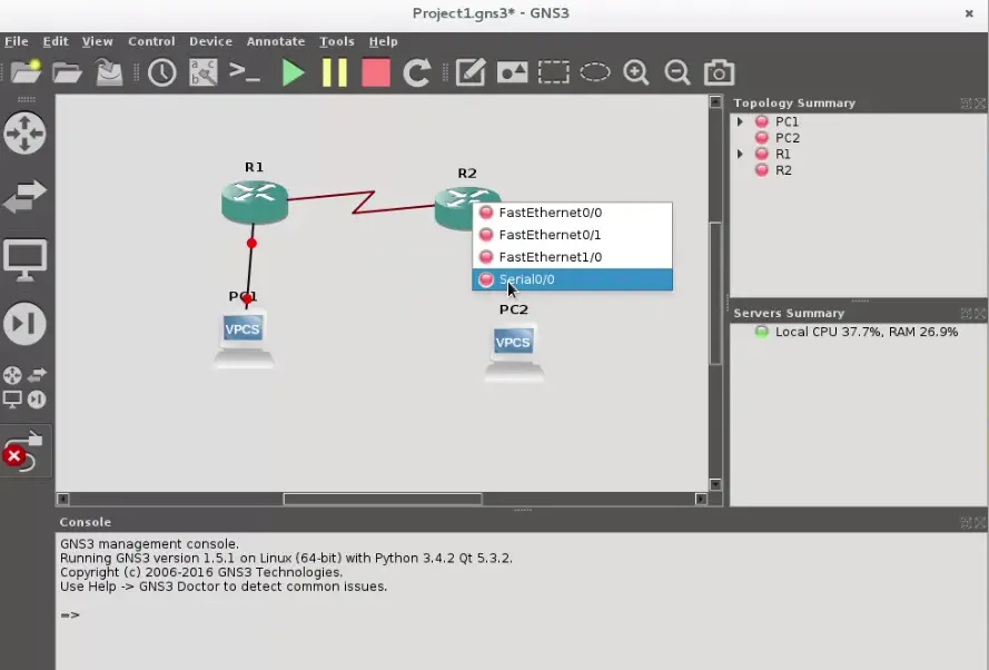
Finally, add links with the respective cables between them. Connect the hosts through the ethernet ports and the routers through the serial ports with the "Add Link" button:
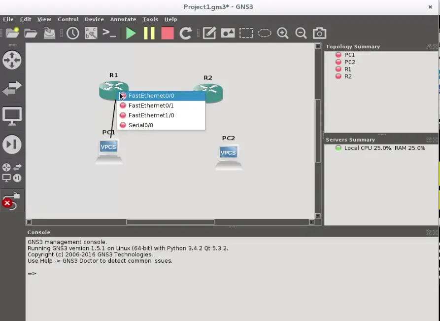
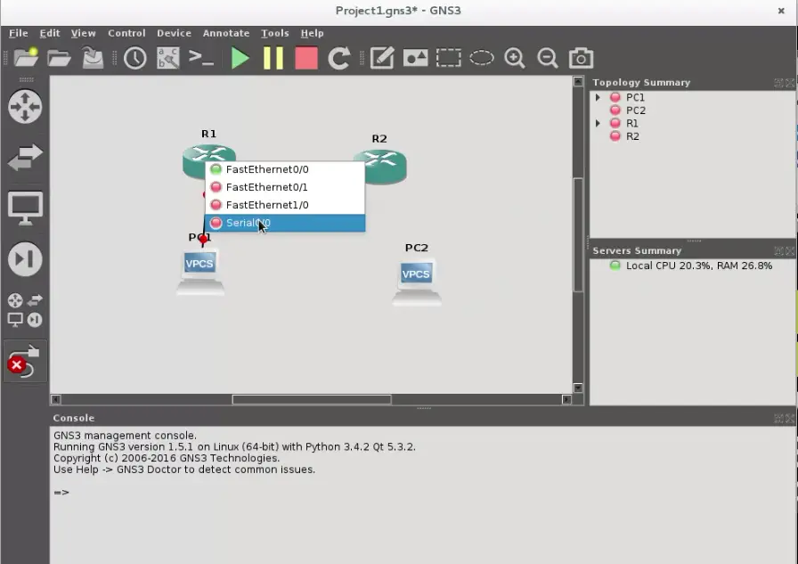
As you will see, the cable type changes for serial ports, because it is a serial cable. The DCE terminal will be in the first router where you start the link, in our case DCE is in R1 router.
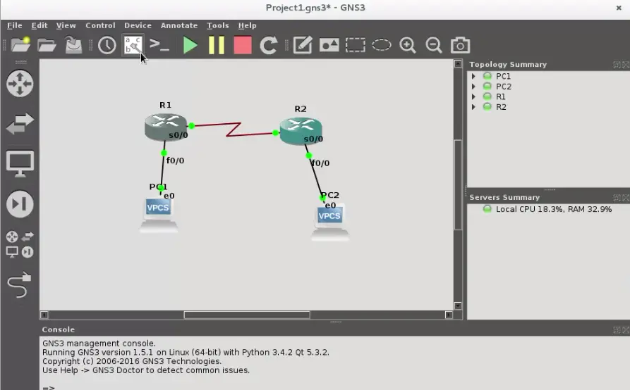
If you want to see the labels of all ports of all devices, then you can push the show/hide label button:

Once finished the topology, we will focus on how routers will be accessed to be programmed.
Starting your Networking Emulation
The first thing we have to do is to click the start devices button.
and you will see that links turn from red color to green, indicating that the emulation has been started.
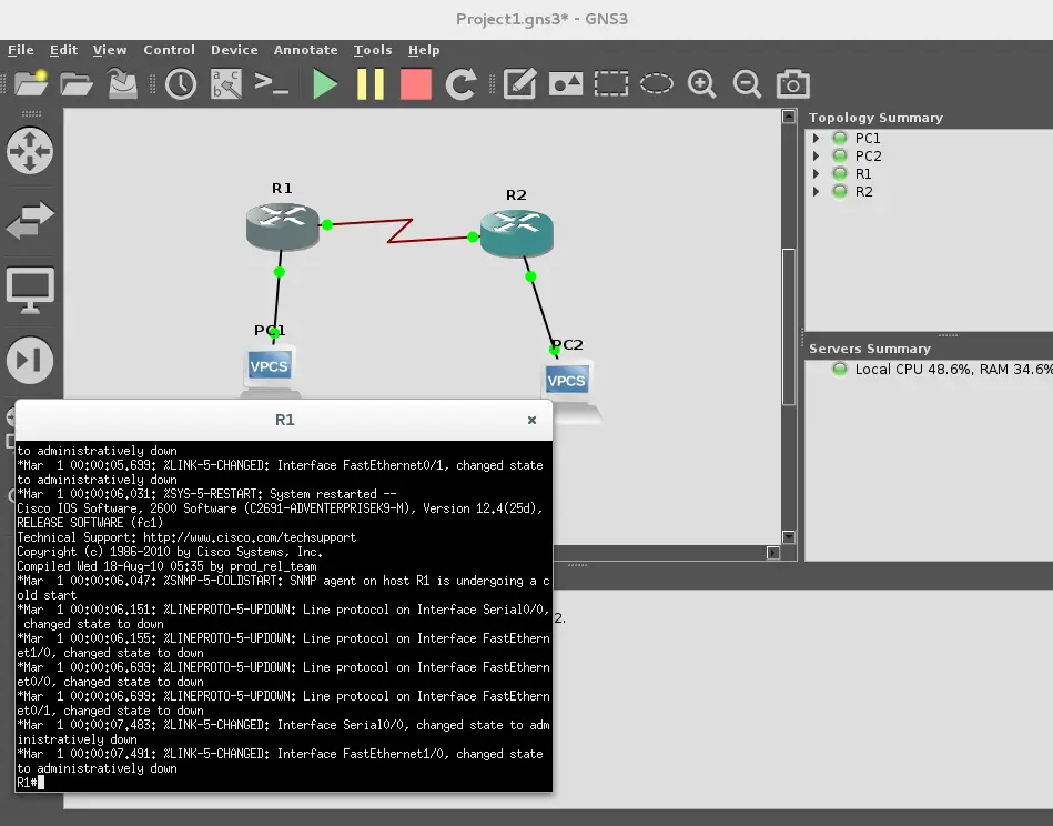
Double click on a router to get the console, and start programming as if you was programming a physical device.
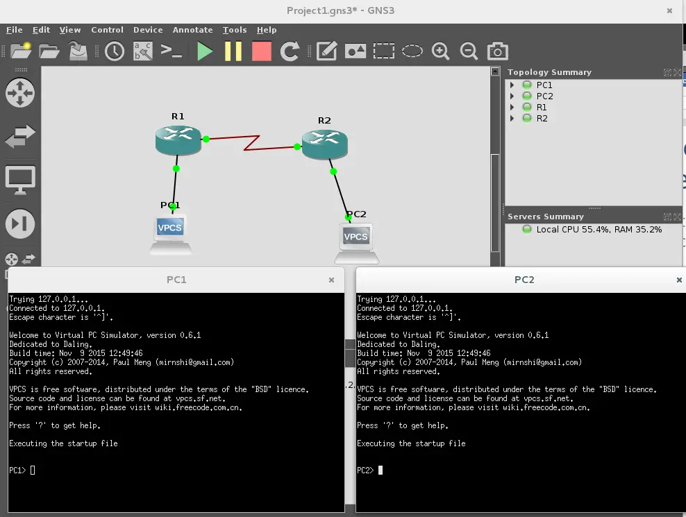
Now you can do a double click on VPCS1 and VPCS2 to assign the respective IP and network mask on each host
This can be done with the command ip, this is the syntax:
ip <address><mask>
where: address is the IP that you want to assign, and mask is the respective network mask. For instance, let's assign the IP address 192.168.1.12/24 in VPC1:
PC1> ip 192.168.1.12 255.255.255.0
Then push enter. To check what you have done use the show command
PC1> show
and you will get this response:
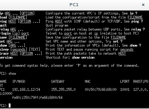
Now we are ready to program our router with the respective network commands. This is not a topic that will be covered in this tutorial, but you have the basis to make the programming steps from now.
I hope you enjoy building your network emulations.

