In May, I wrote an article about building a preamplifier for a moving coil phono cartridge. At the time, I had recently replaced my aging moving magnet cartridge with a nice new moving coil cartridge, and my phono preamplifier did not provide enough voltage gain to directly use the new cartridge. So, after a lot of consideration, I decided to build the Muffsy moving coil preamplifier kit.
It was the first time in years that I’d built something electrical, and I really enjoyed getting out the soldering iron and making this unit. I also appreciated that the Muffsy’s design is open source. The online instructions are excellent. The man behind Muffsy, Håvard Skrodahl, is most kind and helpful, which is great if you’ve messed something up and you're not sure what to do next. The kit's price is most reasonable. And the performance is exemplary.
But what if you have a nice turntable and moving magnet cartridge but no phono preamplifier in your receiver? Maybe you’re one of those 67,000 people in the USA who bought a turntable in 2017? Or you have a pair of powered speakers that you’d like to hook up to the turntable, or maybe a headphone amplifier? In that case, you might be shopping for a phono preamplifier, and one option would be to build the Muffsy phono preamplifier kit. Of course, if you’re really handy you can use the circuit schematics and roll your own from the ground up, but the boards that Muffsy supplies are of exceptionally high quality, so it’s hard not to choose that option.
In any case, I didn’t need a new phono preamplifier, but Håvard had just released a new version—the PP-4—and invited me to build it and compare it with my existing phono section. With my rekindled interest in building electrical stuff, I was happy to accept his invitation. The building process and the results were once again great, and since this kit is of potential interest to anyone thinking of going vinyl, following is a detailed description of my experience with the PP-4.
Note, from the Muffsy website:
The only exceptions to the Creative Commons on muffsy.com is for a few of my PCB designs, mainly variants of those that I'm currently selling. They are free for personal or non-commercial use, but you cannot use them commercially without my approval.
Getting started
The image below shows my desk as I’m getting ready to start the build.
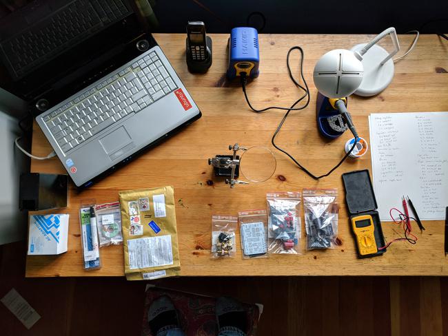
In front of my old Toshiba laptop (which is there to give me access to Muffsy’s build instructions), from left to right are the case and power supply (which must be ordered from other suppliers), a flux pen (haven’t needed this yet), solder wick (ditto), the package in which the kit arrived (covered in cool stamps from far away), the switches and connectors, the circuit boards, a package of DIP switches and stuff, another package of capacitors and resistors and other stuff, my multimeter, and a hand-written inventory of what’s in the packages.
Behind all that, to the right of my laptop is the phone (unrelated), the Hakko soldering station and iron, a nice light, solder, and a magnifying glass on a clamp stand. This is an old desk, so I don’t worry about marking it with dropped tools, liquid solder, or other stuff. It’s also right next to a south-facing window and is very well-lit, an important consideration.
Time to get started!
First, the power supply
The PPA-4 needs high-quality regulated ± 15V direct current power to perform at its best. In my case, I chose to use the Muffsy power supply kit and a 16VAC wall wart recommended on the Muffsy site.
The image below shows the components needed for the power supply:
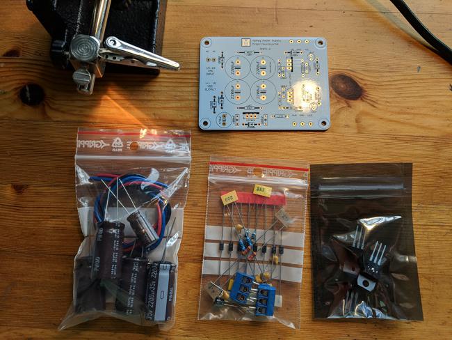
In front, from left to right—the filter capacitors (nice Nichicon electrolytics!) and hookup wire, the resistors, diodes, bypass capacitors and terminal blocks, and the voltage regulator integrated circuits.
Above is the power supply circuit board. The first step is to fit the diodes into the circuit board and solder them in. It can’t hurt to mention that diodes must be oriented correctly; the diodes are marked and the circuit board is marked to match, as shown in the following image:
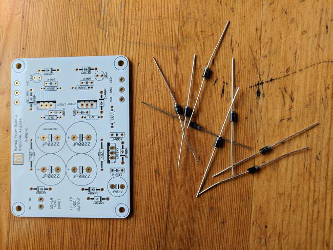
Note that the diodes have a silver band on one edge, and the mounting spots on the board show the outline of the diode with a black stripe at one end. I use a pair of needle-nosed pliers to make nice bends in the metal leads so that the diodes fit into the holes without alignment problems. Once the leads are all through the board, I start soldering. The image below shows the board after I’ve soldered three of the eight diodes.
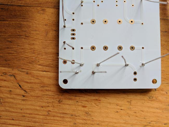
This is a good point to mention a few important things:
-
It’s worthwhile buying a decent soldering iron, ideally temperature-controlled, and decent solder (a very fine solder is best for this kind of work); the soldering video referenced on the Muffsy site is fun to watch and very useful.
-
In my opinion, anyone who is reasonably dextrous and has decent vision can do this kind of work. Yes, the builder must know what the components are, what they do, and so on, but between the Muffsy instructions and all the wonderful background information on the Web, this project requires neither serious geekiness nor the support of a rocket scientist.
-
Patience and comfort and a well-lit workspace make a huge difference to the outcome, in terms of both the enjoyment of the build and the quality of the result.
Jumping ahead a few more steps, here is the board with all of the resistors and diodes soldered in place:
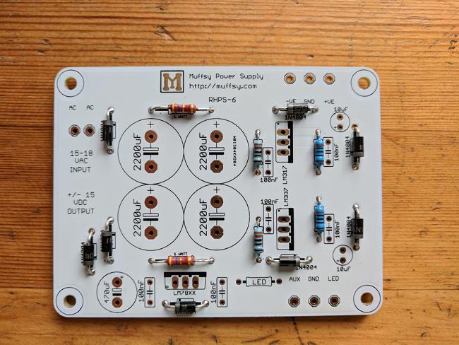
Note that resistors do not require a specific orientation. The colored stripes are a code that gives the value, and I like to make sure that they all read the same way so that I can check one last time to ensure I’ve got the right resistors in the right places. So for example, if we look at the light-blue resistor near the top center of the image, we see the stripes are orange, orange, black, brown, and brown, from top to bottom. Looking at the link noted above, we see this corresponds to 330 X 10¹ = 3300 ohms and the resistor tolerance is 1%. The kit arrives with the resistors tagged with tape displaying their values, but once the tape is gone, the only thing left is the color code. The brown resistors oriented horizontally are 5% (the gold band to the right) and they are yellow, violet, gold, which corresponds to 47 X 10¯¹ = 4.7 ohms (5% resistors have one less digit of precision in their value).
The next image shows the board with the bypass capacitors, voltage regulators, and one filter capacitor mounted.
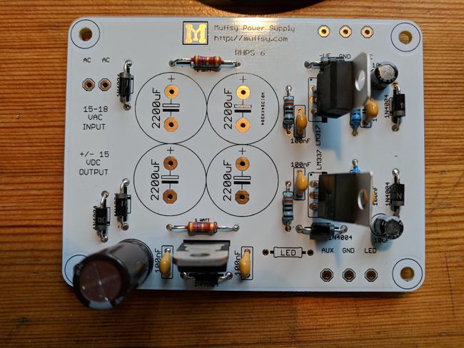
The bypass capacitors are the small golden blobs that say “100nF” beside them. The voltage regulators are standing up from the board with their metal heat sink tabs visible; they must be correctly oriented. The round black cylinder at the lower-left is the filter capacitor, and the gray stripe visible facing downward shows the required orientation.
It’s important to get the orientations correct for those components that require it. At best the circuit won’t work; at worst you might destroy the components. It’s worth double-checking. Again, the instructions are very clear, but nevertheless, I find myself putting things in the wrong way from time to time, and that second check has always found those problems (so far).
The image below shows the final completed power supply with all filter capacitors and the terminal block (for connecting to the preamplifier board) mounted:
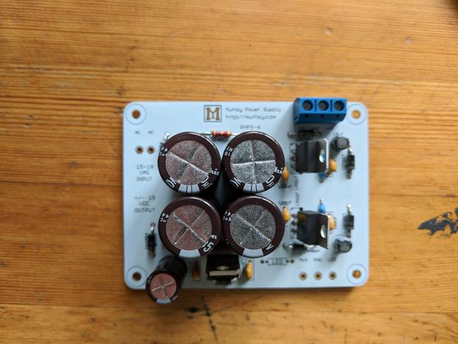
This is a good place to emphasize that this wasn’t hard and it didn’t take a great deal of time. Allowing for all the checking and the photo-taking, it’s about a two-hour task, and for a very high-quality result.
Next, the phono preamplifier
The phono preamplifier has a lot of resistors and quite a few capacitors, as shown in the image below:
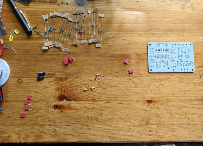
In this image, the strips of tape holding resistors of the same value are visible, along with their labels. The golden blobs are again bypass capacitors. The pink wafers are also capacitors that form a part of the compensation network used to adjust the output of the cartridge so that the frequency response is flat. The black tubes with gray stripes are also capacitors, used to prevent DC from appearing on the output of the preamplifier. And of course, the circuit board is to the right of the image.
The image below shows all the resistors soldered onto the board:
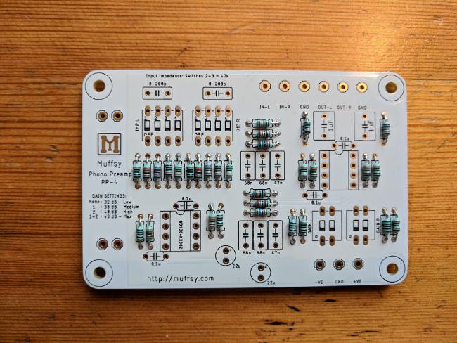
This is a good point to mention that it’s always worthwhile checking that all components are fully soldered to the board. I missed a couple of solder joints as I was soldering and noticed them only on a second inspection.
The image below shows the board with a few more components added:
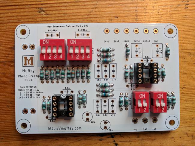
The black squares are the carriers for the operational amplifiers that do the actual amplification in this circuit. It’s possible to solder the amplifiers directly to the board, but it’s also nice to be able to substitute other amplifiers depending on the application, and they’re darned finicky to unsolder. The red switch blocks control the input impedance and gain of the circuit, allowing for use with many different kinds of cartridges.
Putting it all together
The next image shows the two completed boards—power supply and preamplifier—before connecting them and installing the operational amplifiers.
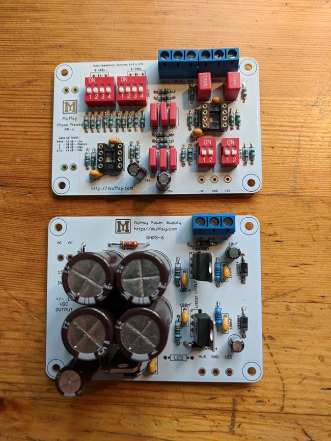
I find the last construction step, which is connecting the boards to each other, to the input and output connectors, and to the power from the wall wart, to be the most difficult. That hookup wire has a mind of its own, and the shielded cable provided is very difficult to strip. Patience and a good wire stripper are essential here.
Here is the finished amplifier in its case and ready for power-up testing:
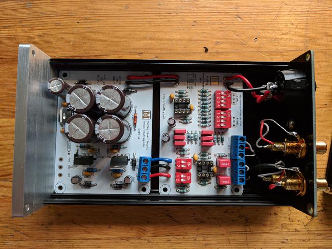
The boards slide into the case and the back plate attaches to the case with screws provided with the kit. At this point, before installing the operational amplifiers, I tested the voltage at various points to make sure all was correctly installed and working properly. The troubleshooting page explains how to do this (not that I was expecting trouble, but it’s good to be sure).
The result
Here I am with my second piece of kit from Muffsy, and I’m as impressed as I was the first time. These are really well-done—not just the boards and materials, but the tremendous organization of the website. And the devices work exceptionally well. I’m impressed with the sound quality from both the pre-preamplifier and the preamplifier.
So, if you have recently acquired (or become interested in) a record player but you have no way to connect it to the rest of your gear—computer, powered speakers, headphone amplifier, or receiver—and are willing to invest some of your own time in building a solution, this is a great option. And in the best spirit of open source, if you’d rather hack your own boards, casework, and power from the designs on the Muffsy site, you’re free to do so.


Comments are closed.