

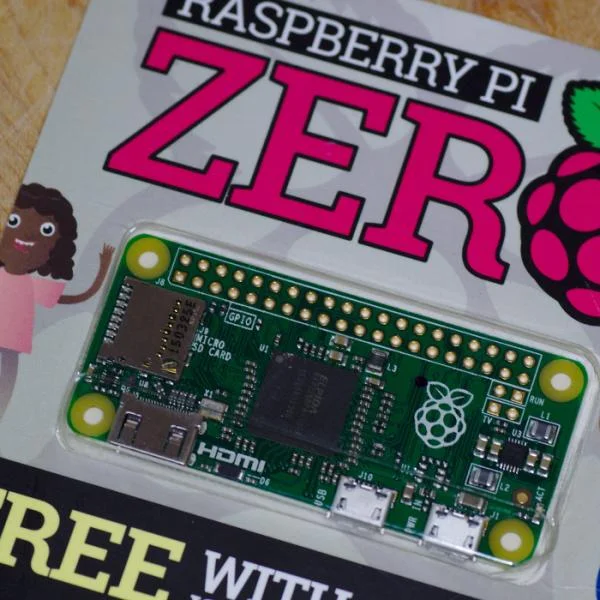
At the tail end of 2015, the Raspberry Pi Foundation surprised the world by releasing the diminutive Raspberry Pi Zero. What's more, they gave it away for free on the cover of the MagPi magazine. I immediately rushed out and trawled around several newsagents until I found the last two copies in the area. I wasn't sure what I would use them for, but I knew their small size would allow me to do interesting projects that a full-sized Pi could not satisfy.
opensource.com
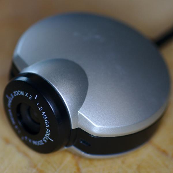
Because of my interest in astrophotography, I had previously modified a Microsoft LifeCam Cinema HD webcam, stripping its case, lens, and infrared cut filter to expose the bare CCD chip. I used it with a custom-built case in place of an eyepiece in my Celestron telescope for astrophotography. It has captured incredible views of Jupiter, close-ups of craters on the Moon, and sunspots on the Sun (with suitable Baader safety film protection).
Even before that, I had turned my film SLR camera into a pinhole camera by drilling a hole in a body cap (the cap that protects a camera's internal workings when it doesn't have a lens attached) and covering it in a thin disc cut from a soda can, pierced with a needle to provide a pinhole. Quite by chance, one day this pinhole body cap was sitting on my desk next to the modified astrophotography webcam. I wondered whether the webcam had good enough low-light performance to capture an image from behind the pinhole body cap. It only took a minute with the GNOME Cheese application to verify that a pinhole webcam was indeed a viable idea.
From this seed of an idea, I had a way to use one of my Raspberry Pi Zeros! The pinhole cameras that people build are typically minimalistic, offering no controls other than the exposure duration and film's ISO rating. Digital cameras, by contrast, have 20 or more buttons and hundreds more settings buried in menus. My goal for the digital pinhole webcam was to stay true to pinhole photography traditions and build a minimalist device with no controls at all, not even exposure time.
The digital pinhole camera, created from a Raspberry Pi Zero, HD webcam, and empty powder compact, was the first project in an ongoing series of pinhole cameras I built. Here's how I made it.
Hardware
Since I already had the Raspberry Pi Zero in hand, I needed a webcam for this project. Given that the Pi Zero retails for £4 in the UK, I wanted other parts of the project to be priced similarly. Spending £30 on a camera to use with a £4 computer board just feels unbalanced. The obvious answer was to head over to a well-known internet auction site and bid on some secondhand webcams. Soon, I'd acquired a generic HD resolution webcam for a mere £1 plus shipping. After a quick test to ensure it operated correctly with Fedora, I went about stripping the case to examine the size of the electronics.
opensource.com
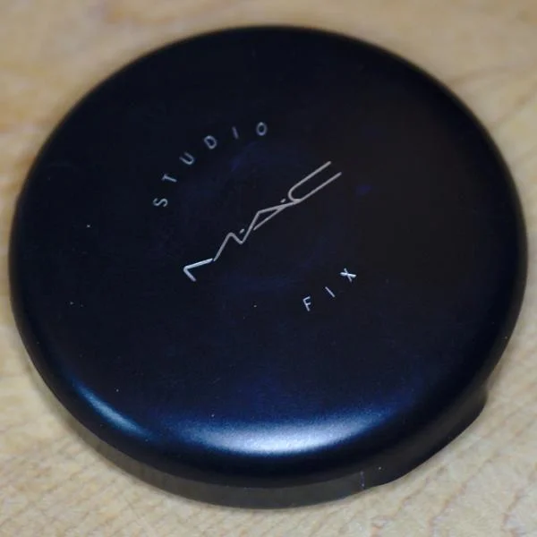
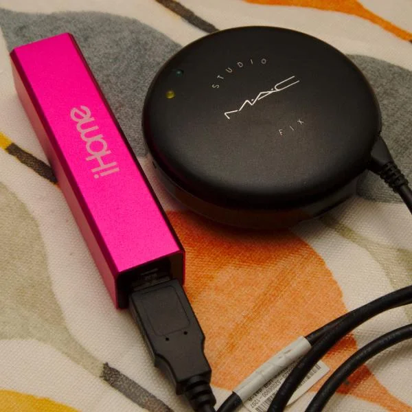
Next, I needed a case to house the camera. The Raspberry Pi Zero circuit board is a mere 65mm x 30mm x 5mm. The webcam's circuit board is even smaller, although it has a plastic mounting around the CCD chip to hold the lens in place. I looked around the house for a container that would fit the two tiny circuit boards. I discovered that my wife's powder compact was just wide enough to fit the Pi Zero circuit board. With a little fiddling, it looked as though I could squeeze the webcam board inside, too.
opensource.com
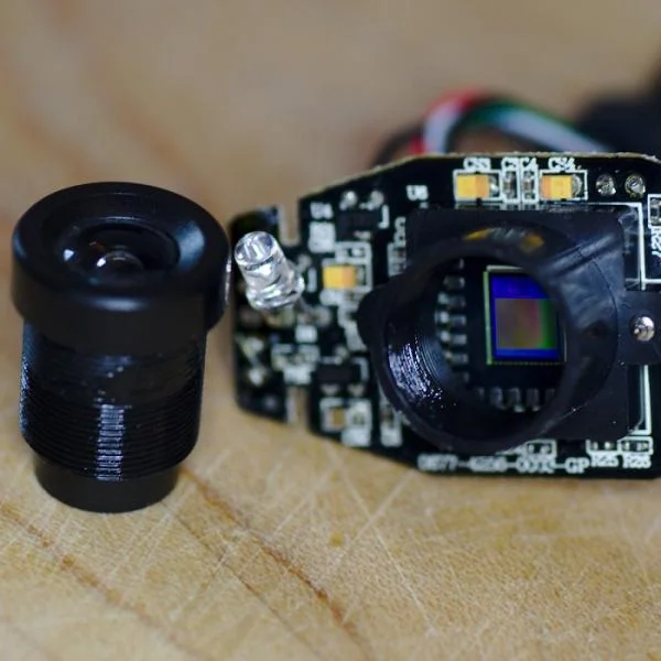
I set out to strip the case off of the webcam by removing a handful of tiny screws to get at the innards. The size of a webcam's case gives little clue about the size of the circuit board inside or where the CCD is positioned. I was lucky that this webcam was small with a convenient layout. Since I was making a pinhole camera, I had to remove the lens to expose the bare CCD chip.
The plastic mounting was about 1cm high, which would be too tall to fit inside the powder compact. I could remove it entirely with a couple more screws on the rear of the circuit board, but I thought it would be useful to keep it to block light coming from gaps in the case, so I trimmed it down to 4mm high using a craft knife, then reattached it. I bent the legs on the LED to reduce its height. Finally, I chopped off a second plastic tube mounted over the microphone that funneled the sound, since I didn't intend to capture audio.
opensource.com
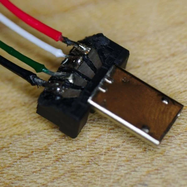
The webcam had a long USB cable with a full-size plug, while the Raspberry Pi Zero uses a Micro-USB socket, so I needed a USB-to-Micro-USB adapter. But, with the adapter plugged in, the Pi wouldn't fit inside the powder compact, nor would the 1m of USB cable. So I took a sharp knife to the Micro-USB adapter, cutting off its USB socket entirely and stripping plastic to reveal the metal tracks leading to the Micro-USB plug. I also cut the webcam's USB cable down to about 6cm and removed its outer sheaf and foil wrap to expose the four individual cable strands. I soldered them directly to the tracks on the Micro-USB plug. Now the webcam could be plugged into the Pi Zero, and the pair would still fit inside the powder compact case.
opensource.com
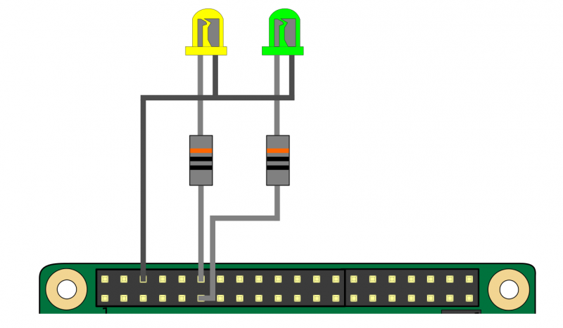
Originally I thought this would be the end of my electrical design, but after testing, I realized I couldn't tell if the camera was capturing images or even powered on. I decided to use the Pi's GPIO pins to drive indicator LEDs. A yellow LED illuminates when the camera control software is running, and a green LED illuminates when the webcam is capturing an image. I connected BCM pins 17 and 18 to the positive leg of the LEDs via 300ohm current-limiting resistors, then connected both negative legs to a common ground pin.
opensource.com
Next, it was time to modify the powder compact. First, I removed the inner tray that holds the powder to free up space inside the case by cutting it off with a knife at its hinge. I was planning to run the Pi Zero on a portable USB power-bank battery, which wouldn't fit inside the case, so I cut a hole in the side of the case for the USB cable connector. The LEDs needed to be visible outside the case, so I used a 3mm drill bit to make two holes in the lid.
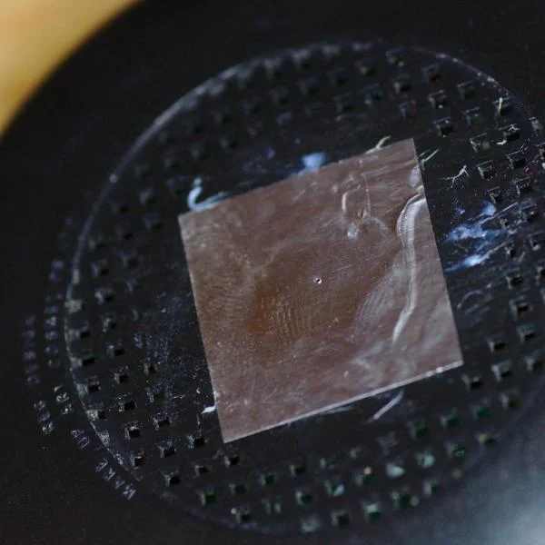
Then I used a 6mm drill bit to make a hole in the center of the bottom of the case, which I covered with a thin piece of metal and used a sewing needle to pierce a pinhole in its center. I made sure that only the very tip of the needle poked through, as inserting the entire needle would make the hole far too large. I used fine wet/dry sandpaper to smooth out the pinhole, then re-pierced it from the other side, again using only the tip of the needle. The goal with a pinhole camera is to get a clean, round hole with no deformations or ridges and that just barely lets light through. The smaller the hole, the sharper the images.
opensource.com
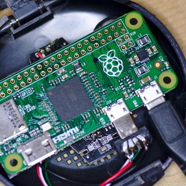
All that remained was assembling the finished device. First I fixed the webcam circuit board in the case, using blue putty to hold it in position so the CCD was directly over the pinhole. Using putty allows me to easily reposition the CCD when I need to clean dust spots (and as insurance in case I put it in the wrong place). I placed the Raspberry Pi Zero board directly on top of the webcam board. To protect against electrical short circuits between the two boards, I covered the back of the Pi in several layers of electrical tape.
The Raspberry Pi Zero was such a perfect fit for the powder compact that it didn't need anything else to hold it in position, besides the USB cable for the battery that sticks out through the hole in the case. Finally, I poked the LEDs through the previously drilled holes and glued them into place. I added more electrical tape on the legs of the LEDs to prevent short circuits against the Pi Zero board when the lid is closed.
opensource.com
Software
Computer hardware is useless without software to control it, of course. The Raspberry Pi Zero can run the same software as a full-sized Pi, but booting up a traditional Raspbian OS image is a very time-consuming process due to the Zero's slow CPU speed. A camera that takes more than a minute to turn on is a camera that will not get much real-world use. Furthermore, almost nothing that a full Raspbian OS runs is useful to this camera. Even if I disable all the redundant services launched at boot, it still takes unreasonably long to boot. I decided the only stock software I would use is a U-Boot bootloader and the Linux kernel. A custom written init binary mounts the root filesystem from the microSD card, loads the kernel modules needed to drive the webcam, populates /dev, and runs the application binary.
The application binary is another custom C program that does the core job of controlling the camera. First, it waits for the kernel driver to initialize the webcam, opens it, and initializes it via low-level v4l ioctl calls. The GPIO pins are configured to drive the LEDs by poking registers via /dev/mem.
With initialization out of the way, the camera goes into a loop. Each iteration captures a single frame from the webcam in JPEG format using default exposure settings, saves the image straight to the SD card, then sleeps for three seconds. This loop runs forever until the battery is unplugged. This nicely achieves the original goal, which was to create a digital camera with the simplicity on par with a typical analog pinhole camera.
The code for this custom userspace is made available under GPLv3 or any later version. The Raspberry Pi Zero requires an ARMv6 binary, so I built it from an x86_64 host using the QEMU ARM emulator to run compilers from a chroot populated with the toolchain for the Pignus distro (a Fedora 23 port/rebuild for ARMv6). Both binaries were statically linked with glibc, so they are self-contained. I built a custom RAMDisk containing the binaries and a few required kernel modules and copied it to the SD card, where the bootloader can find them.
opensource.com
Taking photos
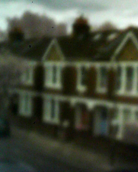
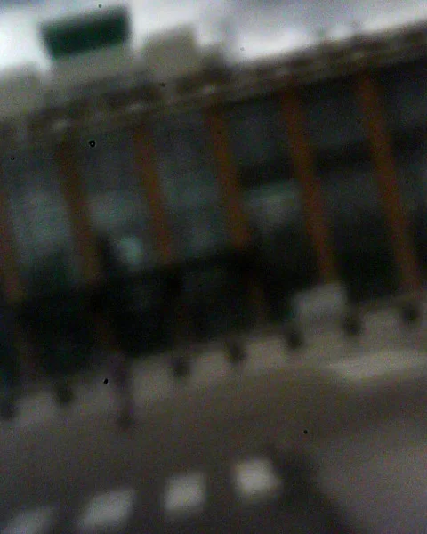
With both the hardware and software complete, it was time to see what the camera was capable of. Everyone is familiar with the excellent quality of images produced by modern digital cameras, whether professional DSLRs or mobile phones. It is important to reset expectations here to a more realistic level. The HD webcam captures 1280x1024 resolution (~1 megapixel). The CCD struggles to capture an image from the tiny amount of light allowed through the pinhole. The webcam automatically increases gain and exposure time to compensate, which results in very noisy images. The images also suffer from a very narrow dynamic range, as evidenced by a squashed histogram, which has to be stretched in post-processing to get true blacks and whites.
The best results are achieved by capturing images outside in daylight, as most interiors have insufficient illumination to register any kind of usable image. The CCD is only about 1cm in diameter, and it's just a few millimeters away from the pinhole, which creates a relatively narrow field of view. For example, in a selfie taken by holding the camera at arm's length, the person's head fills the entire frame. Finally, the images are in very soft focus, which is a defining characteristic of all pinhole cameras.
opensource.com
opensource.com
Initially, I just used the camera to capture small numbers of still images. I later reduced the loop delay from three seconds to one second and used the camera used to capture sequences of images over many minutes. I rendered the images into time-lapse videos using GStreamer.
Here's a video I created with this process:
Video of the walk from Bank to Waterloo along the Thames to unwind after a day's work. 1200 frames captured at 40 frames per minute animated at 20 frames per second.


Comments are closed.